Simulation of Activated Carbon Reactors
What are the benefit of hydrograv simulations?
- proof of the flow conditions and improved mixing and hydraulic residence time
- efficient dimensioning of agitators
- prevention of depositions
- maximization of separation in the settling tank
Example 1: Measurement of settling velocities
- investigation of sludge properties
- settling tests
- calibration of the settling models
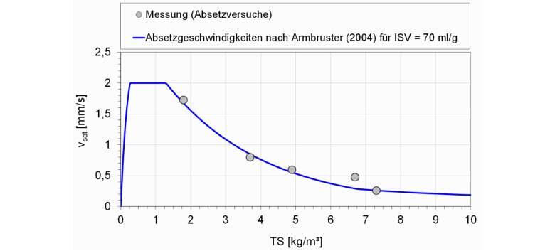
Figure: Comparison between measured and simulated settling velocities.
Example 2: Simulation of a contact reactor with inner settling tank
- optimization of mixing in the reactor
- maximization of particle separation in the settling tank
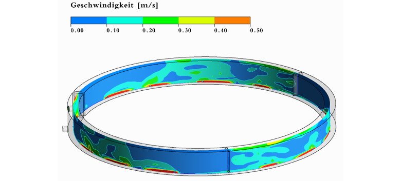
Figure: Flow velocities in the contact reactor designed as a ring-shaped tank.
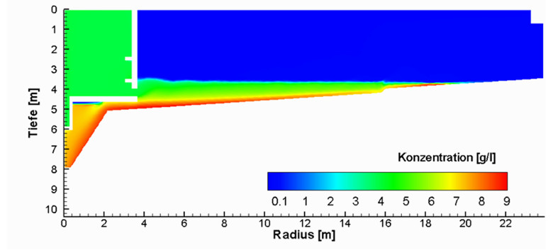
Figure: Concentration of a mix of activated carbon and activated sludge in a settling tank. Illustration on a vertical plane.
Example 3: Optimization of a contact reactor
- optimization of the number of agitators, the agitator’s thrust and their orientation
- installation of deflection baffles
- minimization of depositions
- minimization of the energy consumption for mixing
- proof of different loading cases: the preferred variant is the best compromise between dry weather and stormwater flow
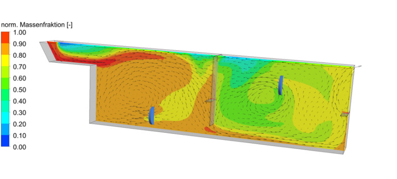
Figure: Distribution of particles as normalized mass fraction.
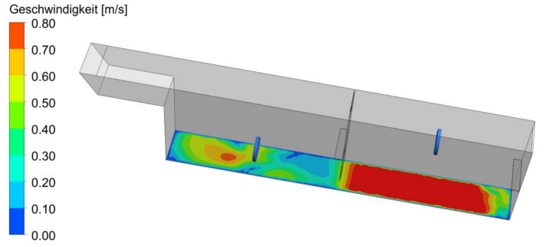
Figure: Velocities close to the bottom as proof for depositions.
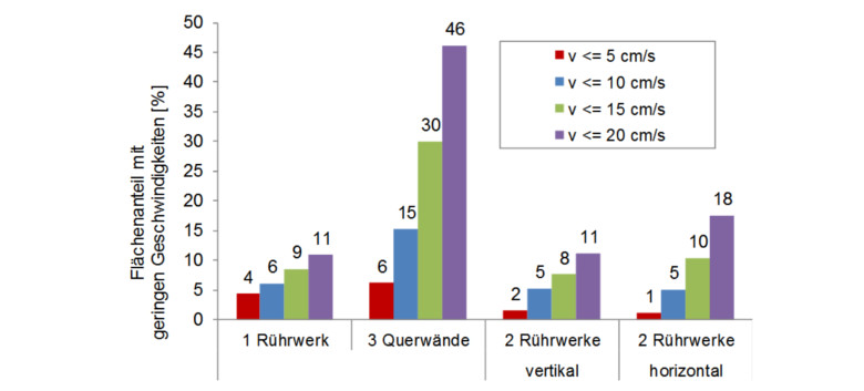
Figure: Deterministic analyses of the velocities close to the bottom as proof for depositions.
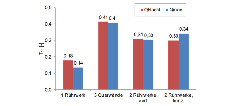
Figure: Statistical analyses of a tracer simulation, here showing the 10 %-percentile as proof for short-circuit flows.