Sewer Structures
What are the benefits of hydrograv simulation?
In addition to pipelines the sewage system consists of numerous additional structures that drain off wastewater or rainwater from sewage pipes to wastewater treatment plants or to other treatment points. The hydraulic situation in sewer structures is often complex and cannot always be predicted with sufficient accuracy using conventional design approaches.
With hydrograv simulations complex flow processes can be realistically modeled and, for example, flow rates, water levels or hydraulic and material distributions can be precisely determined. This increases planning reliability.
Existing hydraulic problems can also be identified with relatively little effort and solutions can be developed in a targeted manner.
hydrograv simulations can be used, for example, for
- channels and pipelines
- manholes
- separating structures
- vortex manholes
- retention basins
.
Determination of realistic hydraulic losses
In any real moving fluid, energy is dissipated due to friction and above all due to turbulence. This applies in particular in the case of complex interactions between different structures. Thus, without simulation a sufficiently precise prediction of the water levels and the associated flows separation in separation structures is not possible .
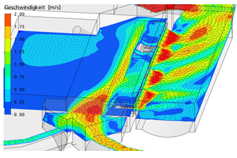
In the next picture a hydraulic situation within a separating structure with bar screens on the weir is shown. hydrograv simulations made it possible to achieve a more uniform flow through the bar screens and to avoid unwanted backwater by optimizing the channel cross-sections downstream.
.
Solving complex problems with profound hydraulic expertise
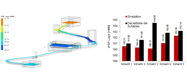
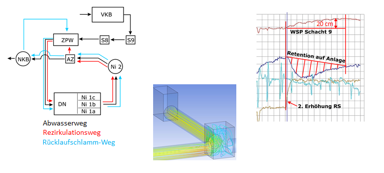
In the following example a sewer manhole flooded a wastewater treatment plant for inexplicable reasons. hydrograv simulations determined a 25 cm higher hydraulic loss in the sewer system than calculated analytically. However, since there is a freeboard of 35 cm in the manhole this alone does not explain the overflow.
Only the analysis of various hydrographs shows that an unfavourable recirculation flow strategy in the secondary clarification leads to a backwater effect in the entire system of the wastewater treatment plant and causes the water level in the manhole to rise by a further 20 cm and thus exceeds the freeboard in the shaft by 10 cm.
.
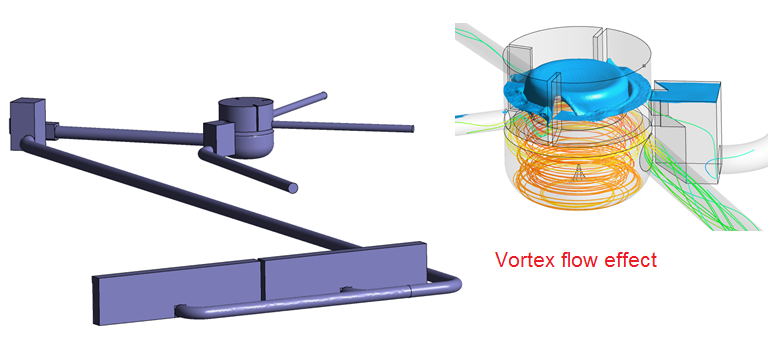
Unexplainably high hydraulic losses
In the inflow system for a secondary clarification inexplicably high hydraulic losses occur which remains a puzzles to the operator. A hydrograv simulation can show that an unwanted vortex flow effect in the distribution structure leads to hydraulic losses of approx. 45 cm. The loss can be reduced to 15 cm by optimization.