Simulation of Grit Chambers
What are the benefits of hydrograv simulations?
- Maximization of removal rates of grit particles and grease
- Minimization of construction costs by efficiency increase (e.g. less construction volume)
- Minimization of operational costs by optimization of the aeration
- Determination of dynamic forces on installations
Example 1: Calibration and validation of the simulation models for aerated grit chambers
- Measurements of the 3D-velocity by a high resolution acustic probe
- Calibration and validation of model approaches, e.g. turbulence model, bubble size
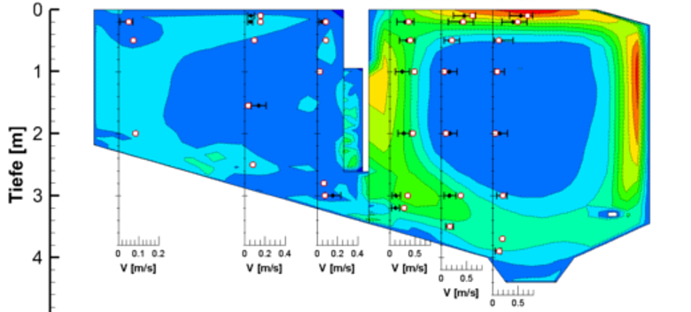
Figure: Comparison of measured and simulated water velocities in the grit and grease basin of an aerated grit chamber.
Example 2: Streamlines visualize the flow patterns
- Streamlines visualize the path of the flow and show areas with hydraulic deficits, e.g. short-circuit flow.
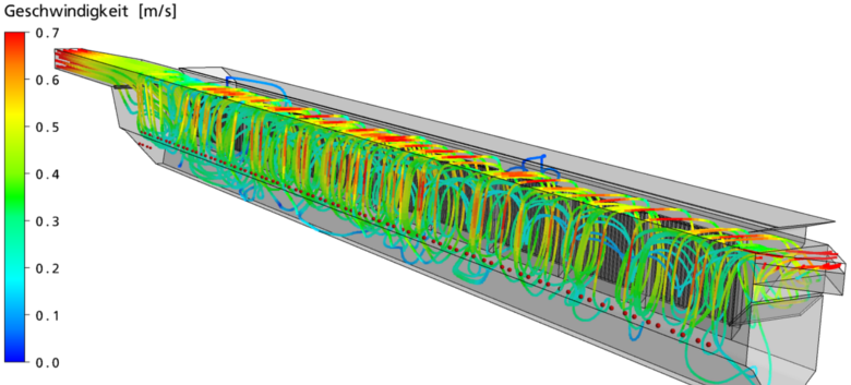
Figure: Streamlines with velocities vizualize the flow patterns.
Example 3: Investigation of geometrical changes
- for example, investigation of the impact of a separation baffle between grit and grease basin
- deterministic analysis of the removal rate of grit and grease
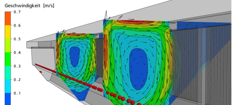
Figure: Aerated grit chamber with lamellae as a separting wall between grit and grease basin.
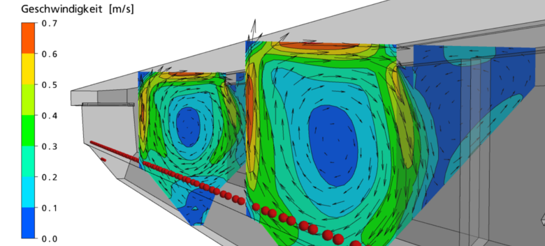
Figure: Aerated grit chamber without lamellae as a separting wall between grit and grease basin.
.
Example 4: Verification of separation rates
- simulation of test sand according to the German Association for Water, Wastewater and Waste, DWA (2008): Arbeitsbericht des DWA-Fachausschusses KA-5 „Absetzverfahren“. Sandfänge – Anforderungen, Systeme und Bemessung. Korrespondenz Abwasser, Abfall 5/2008. S. 508 – 518.
- Investigation of different classes of materials: sand, grease, organic substances
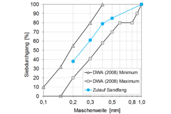
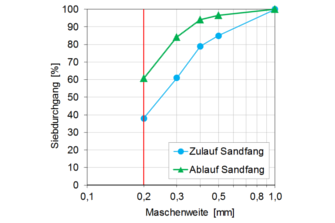
Figure: Grain distribution of sand. Left: at the inlet of the grit chamber. Right: Comparison between inlet and outlet of the grit chamber. Mesh width logarithmic.
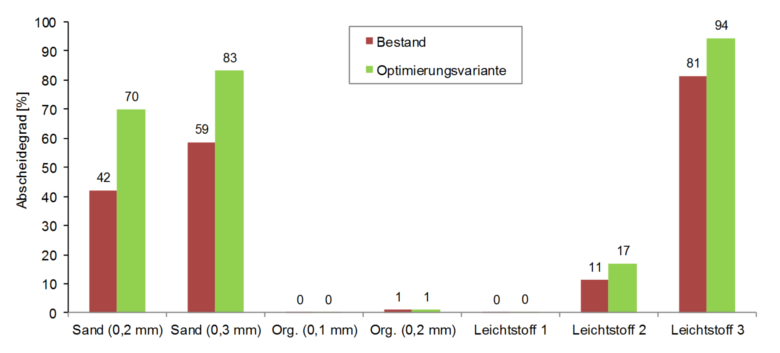
Figure: Separation rate of different classes of materials.
.
Example 5: Verification of dynamic forces
- Determination of the hydrodynamic pressure on the basis of the flow velocity on the total surface of a separating wall pipes and determination of the force acting therefrom
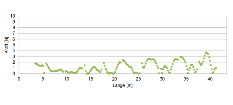
Figure: Dynamic forces acting on separating wall pipes between grit and grease basin.